Last update:May.18th.2012
| Version | Last update | Edited by | Approved by | Edition |
|---|---|---|---|---|
| A01 | 11th.May.2012 | Yuki koike | First edition | |
| A02 | 18th.May.2012 | Yuki Koike | Amended Contants and pointed-out points | |
| A03 | 21st.May.2012 | Yuki Koike | Mr.Ohnuma | Amended pointed-out points |
Contants
-
This document shows process of dismantlement of MIRS1101.
This also tells characteristics of MIRS1101.
1.Note
-
- Remove the Super Sonic Sensor board
- Remove the bumper
- Remove the Motor Contorol board
- Remove the Power supply board
- Remove the upper chassis
- Remove the Web camera
- Remove the electric circuit cover
- Remove the Posts (both of larger and shorter)
- Remove the Touch Sensor
- Remove the DOTA board (both of upper and lower)
- Remove the Cables
- Remove the Super Sonic Sensor board
2.Process of dismantlement
3. Characteristics of MIRS1101
-
The Super Sonic Sensor board , the Motor Contorol board and the Power Supply board which would be required to debug frequntly were deployed.
Fig.1 Upper row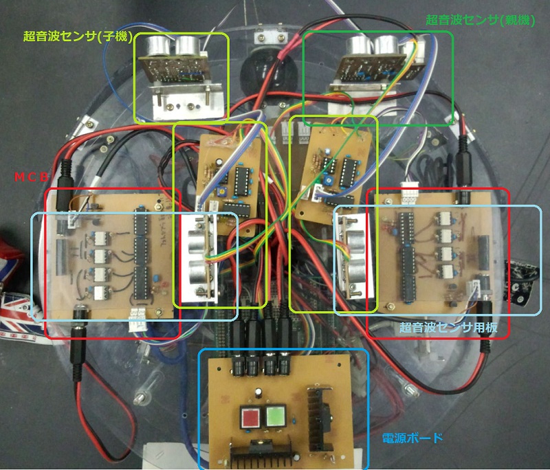
3-1-1 The bumper
3-1 Upper row
The material of the bumper , which protected the camera ,was altered to acrylic plastic.
It is guessed by MIRS1204 that purpose of alteration was to reduce load of the Motor and to maintain easily by losing weight.
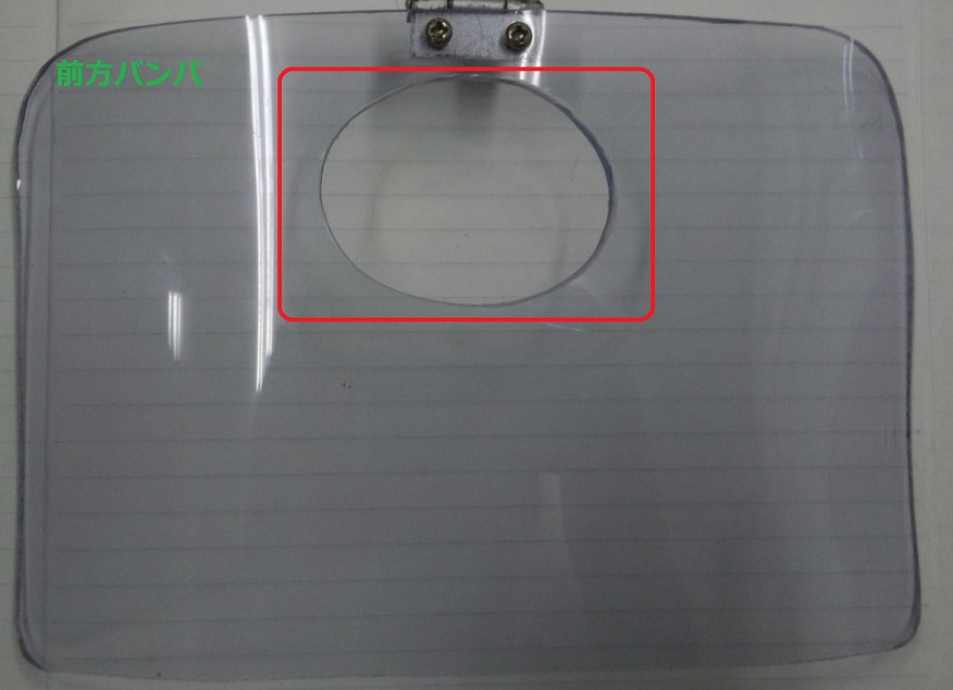
Fig.2 The bumper
3-1-2 The Super Sonic Sensor board (Specification of manufacturing the Super Sonic Sensor board) 3-1-3 The Motor Control board 3-1-4 The Power Supply board 3-1-5 Whole of Upper row 3-1-6 The chassis To get more information about alternation , refer to following the documents. 3-1-7 The Posts To get more information about alternation , refer to following the documents. 3-2-1 The Web camera 3-2-2 The touch sensor 3-2-3 The cable 3-2-3 The DOTA board , the CPU board 3-3-1 The line detector 3-3-2 The springs 3-3-3 The ballcaster 3-3-4 The tyres
The oscillator and the Super Sonic Sensor were separated each other on the side of main body.
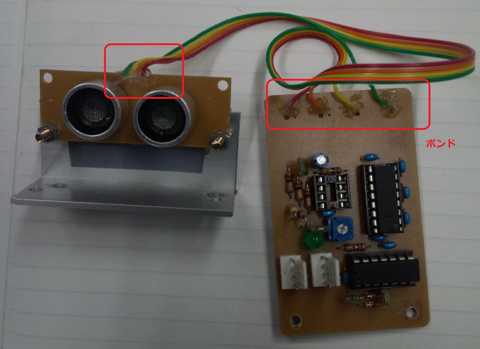
Fig.3 The Super Sonic Sensor
There was the oscillator in the centre of the chassis.
Because the MIRS1101 members added two surpluse Super Sonic Sensor , MIRS1101 had three sensors on it.
There were smooth plastic covers beside of Super Sonic Sensor , and the MIRS1204 members guessed two Super Sonic Sensor covers availed of restraining the affect , covering with a flat board on the eletric circuit.
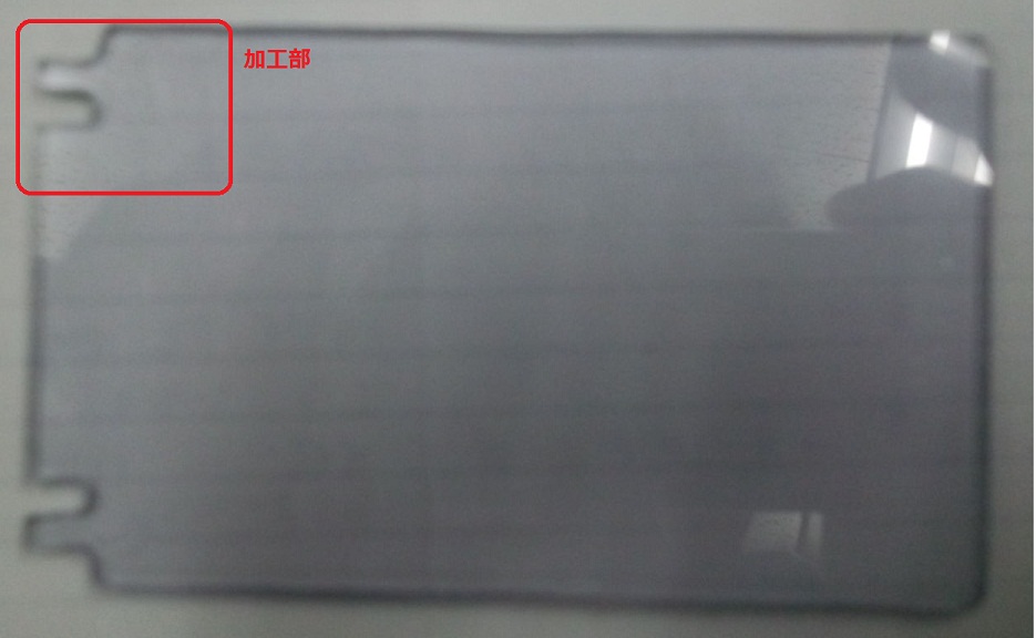
Fig.4 The flat electric circuit cover
The MIRS1204 members have confirmed that wasn't changed from normal MIRS.
Specification of manufacturing MTCB
The MIRS1204 members have confirmed that wasn't changed from normal MIRS.
Satification of manufacturing The Dual Regulator Power Supply board
The connection units were altered to avoid the errors occured from disconnection.
The MIRS1204 members guessed it was set to save repairing time.
The alteration of material to the plastic allowed to MIRS to be lighter.
The MIRS1204 members guessed that circle shape adopted by MIRS1101 was formed so as to pass the corner smoothly.
Specificatin of manufacturing upper row chassis
The MIRS1101 members could success to reduce weight by altering the material to acrylic.
It also contributed to make the manuracturing ease.
3-2 Middle row
The MIRS1204 members confirmed it wasn't changed from normal machine.
There were 3 touch sensors in front of main body of the machine.
But the normal machine has only one touch sensor in front , MIRS1101 had 3 sensors set by its front shape , curve.
The MIRS1204 members thought the MIRS1101 members used this system to make MIRS become sensitive to detect crash from any side of its front.
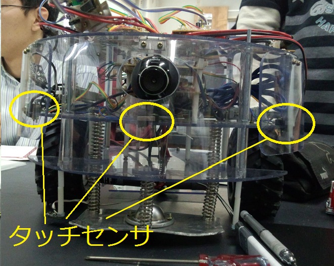
Fig.6 The Touch sensor
Some of connection unit were changed from ① to ② so as to withstand from any vibrations.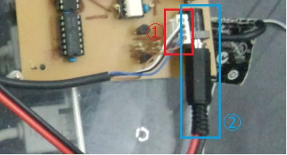
Fig.7 Changed connection units
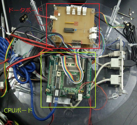
The MIRS1101 had 2 boards which were arrenged in parallel.
The MIRS1204 members guessed that the members of MIRS1101 had adopted this structure to make MIRS stable and make maintenance easy.
3-3 Lower row
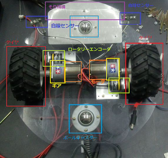
Fig.8 Lower row
The MIRS1204 members have confirmed it wasn't changed from normal machine.
Process of normal machine
The springs which aren't installed in normal machine were installed in MIRS1101.
The springs located between middle row and lower row , and in front of its body and in back of its body.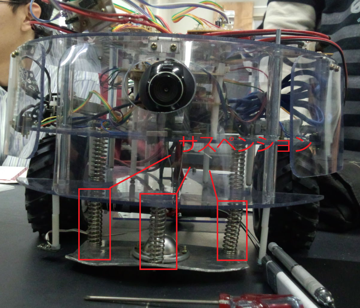
Fig.9 The saspetions
The front-located saspention was set with the bended board which connected with caster.
Each saspention had the ballcaster in center of it so as not to be ovstructed by the any obstacles , such as the step and the seesaw.
Refer to Fig.8 Lower row
The suspentions were linked with , the 2 springs on the middle row , and , the 3 springs on the lower row.
The members of MIRS1204 guessed that , the 3 springs with lower row had been installed to pass the obstacles smoothly , and , the 2 springs with middle row had been installed to reduce the shock by occuring when MIRS passed the bumps.
The members of MIRS1204 have confirmed it was'n changed from normal machine.
Process of assembling the normal machine
The members of MIRS1204 have confirmed it was'n changed from normal machine.
Process of assembling the normal machine
Dep.Degital engineering , Numazu national college of technology